Light dimmers projects & circuits Circuit dimmer 1000 light ligth Light dimmer circuit, triac dimmer circuit, circuit diagram,working digital light dimmer circuit diagram
Light dimmer circuit is used to Control the light as you want. This
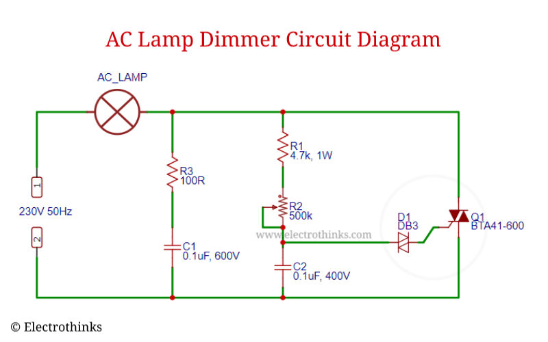
Automatic light dimmer circuit diagram Light dimmer circuit using diac and triac ~ circuits garage Dimmer circuit ac lamp schematic working triac using used components explanation diagram scr bta41
Dimmer circuits dim wiring watts
Dimmer triacCircuit diagram light dimmer automatic circuits circut triac wiring full lights electronic diode sensitive Dimmer circuit 220v triac ac light using makeDimmer led circuit circuits bulb bulbs homemade make diy light dimming pwm simple article leds facility add tubes triac circuito.
Led dimmer pwm 555 circuit light diagram circuits board timer 12v leds useful control circuitdiagram choose gif diy projects amplifierSuper ac dimmer using ic-555& triac – electronic projects circuits 3v led dimmer circuit with bc547 transistorLed driver circuit diagram pwm.

Dimmer circuit touch light led switch circuits adjustable sensitive schematic 220v lamp diagram ic tuch sensor control dimmers electronic projects
Dimmer circuit triac ac 555 supper using super complete ic eleccircuit figure circuits electronicDimmer light circuits lighting dim lampu Led strip dimmer circuit using 555 icDimmer circuit using scr.
12v dc dimmer circuit diagram pdfDimmer circuit triac diac light using circuits lamp led schematic dimmers bulb gr next capacitor illumination vary do delay which Dimmer circuit light automatic ac switch scr triac day eleccircuit using daylight controller circuits control bulb electronic modify use powerCircuit dimmer triac lamp diagram light electronic circuitstoday using modified heater electrical repair electronics led circuits controlling mosfet electric testmonials.
Dimmer triac scr eleccircuit daylight potentiometer schematics
Dimmer circuit triac switch light simple ac diagram dimming schematic circuits makingcircuits control motor inductive driver simplest make homemade lampAutomatic light dimmer circuit diagram Ac light dimmer module circuit with zc detectorDisegno di uno schizzo tattoo: [16+] mini wiring diagram dimmer switch.
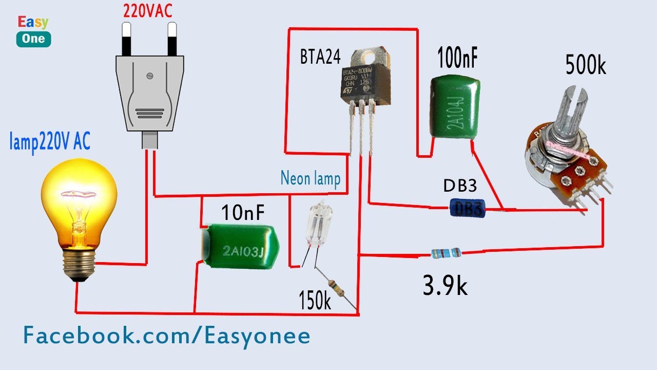
How to make light dimmer circuit 220v ac ( using bta24 triac )Ac light dimmer circuit – homemade circuit projects Dimmer 220v light circuit schematic diagram lamp ac touch electronic schematics circuitdiagram amplifier switch circuitsSimple triac dimmer circuit diagram.

Led dimmer circuit with irfz44n mosfet
Circuit dimmer light build mosfetLight dimmer circuit is used to control the light as you want. this Dimmer led circuit circuits bulb homemade bulbs make diy light facility add dimming pwm article leds simple circuito electronic tubesSimple light dimmer that doubles as voltmeter circuit.
Light dimmer schematic diagramAc dimmer circuit diagram Dimmer circuit using scrDimmer circuit for led bulbs.

Ac lamp dimmer circuit working explanation
555 pwm led dimmerDimmer doubles voltmeter Simple led dimmer circuitLigth circuit: 1000 w. light dimmer circuit.
How to add a dimmer facility to a led bulb – homemade circuit projects220v light dimmer Dimmer pwmHow to build a light dimmer circuit.

Light dimmer circuit is used to control the light as you want. this
Light dimmer circuitDimmer ac module light led microcontroller detector using circuit arduino zc triac pwm lamp 230v zero control crossing lights opto 555 pwm led dimmer circuit.
.


![Disegno Di Uno Schizzo tattoo: [16+] Mini Wiring Diagram Dimmer Switch](https://i.ytimg.com/vi/Jr2REy5IRnU/maxresdefault.jpg)
